OpenBIMRL | Anatomy OpenBIMRL Graph
Nodes
OpenBIMRL graphs consist of interlinked nodes. These nodes represent a wide variety of operations which, through clever linking, can represent complex rule checks.
Node Types
First of all, all nodes can be divided into three categories, each marked by a different color.
- Input-Nodes (yellow)
- Operator-Nodes (white)
- Output-Nodes (red)
Input-Nodes
Each input node is adapted and built according to its functionality. However, each of them is used to feed user input into an openBIMRL graph and has at least one output. As a rule, input nodes can be further customized by double-clicking on them - an exception to this is the switchInput.
textInput
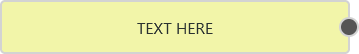
The textInput consists of an input field and a single output. By double-clicking, the input value can be changed and can accept any value in the form of a string. This also includes numerical values and booleans.
distributorInput

WIP
colorInput
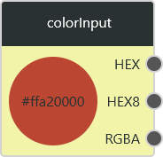
The colorInput has three outputs and a visualization of the current color value. By doubel-clicking on the input, a color can be entered via various options. On the one hand, the color can be set via the large color field and the sliders for hue and opacity or via the corresponding numerical values directly, both the hexadecimal notation and the notation in the RGBA color space exist. Note, however, that the numerical values for RGB must be in the integer range from 0 to 255 and the numerical value for A must be a floating point value in the range between 0 and 1. The three outputs are given in HEX, HEX8 and RGBA. RGBA outputs numeric values from 0-255 for RGB and 0-1 for A. HEX8 outputs these values in the hexadecimal system. HEX gives these color values without information about opacity (A in RGBA).
numberSliderInput
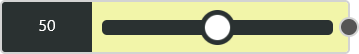
The numberSliderInput outputs a numerical value that can be set variably via a slider. By double-clicking, further settings can be made on the slider. So the minimum, the maximum, the step size and the current value can be set manually.
switchInput
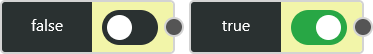
The switchInput outputs a boolean. For this purpose, the status can be changed between "true" and "false" via the switch.
Operator-Nodes
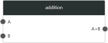
An operator node is a node that takes input values and calculates output values based on them using a function. For this purpose, an operator node can accept any number of input values and generate any number of output values, these being either simple values, lists or trees (see standard behavior). The name of the corresponding operator node is displayed at the top center.
Output-Nodes

The RuleIdentifier node gives the user the ability to name outputs and have them selected as operands in the rules.
Status (WIP)
Verschiedene Status eines Blocks erklären. Farblich gekennzeichnet durch Änderung der Rahmenfarbe.
Grün = Erfolgreiche Berechnung Rot = Error in irgendeiner Form Blau = Kopiert
Node use cases
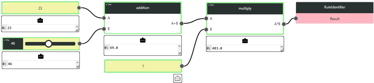
After executing a graph, the console can be viewed at each node to understand the outputs at each point in the graph. In addition, the user is informed about the status of each node.